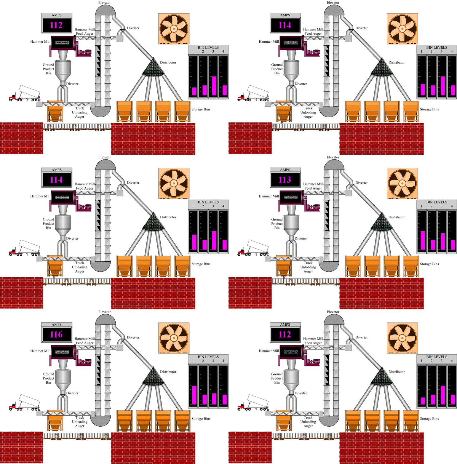
SCADA (supervisory control and data acquisition) is a type of software application and hardware control that defines the way data and real-time processing is controlled. You mostly find SCADA in every industries such as power plants and oil and refining businesses. You can also find SCADA rules in telecommunications and transportation.
What is the Scada system?
SCADA (supervisory control and data acquisition) is a system, operates with coded signals over communication channels so as to provide control of remote equipment (using typically one communication channel per remote station.
Acronym for supervisory control and data acquisition, a computer system for gathering and analyzing real time data. SCADA systems are used to monitor and control a plant or equipment in industries such as telecommunications, water and waste control, energy, oil and gas refining and transportation. A SCADA system gathers information, such as where a leak on a pipeline has occurred, transfers the information back to a central site, alerting the home station that the leak has occurred, carrying out necessary analysis and control, such as determining if the leak is critical, and displaying the information in a logical and organized fashion. SCADA systems can be relatively simple, such as one that monitors environmental conditions of a small office building, or incredibly complex, such as a system that monitors all the activity in a nuclear power plant or the activity of a municipal water system or other plants.
What is meant by PLC Scada?
Programmable Logic Controller or PLC is a computing system used to control electromechanical processes. SCADA stands for Supervisory Control and Data Acquisition. It is a type of industrial control system that is used to monitor and control facilities and infrastructure in industries.
What is Scada network?
Acronym for supervisory control and data acquisition, a computer system for gathering and analyzing real time data. SCADA systems are used to monitor and control a plant or equipment in industries such as telecommunications, water and waste control, energy, oil and gas refining and transportation.
What is meant by supervisory control?
Supervisory control is a general term for control of many individual controllers orcontrol loops, whether by a human or an automatic control system, although almost every real system is a combination of both.
What are some different levels of SCADA machines and systems?
SCADA machines have several different forms. You can have field level devices such as sensors. You can have remote terminal units (RTUs), a main controller or “master station,” or you can have a simple computer system interface that displays data for the user.
Why SCADA systems are Implemented?
Some of the reasons or advantages why SCADA systems are implemented are.
SCADA systems improves the performance of the operation of the plant
SCADA systems provides better protection to the equipment of the plant
SCADA systems improves productivity of the personnel
Information receives very fast, process the information and display it to opertor in graphs and plots. Hence helps the operator to take the decisions fast.
Provides better energy savings and saves economy
Why do companies use SCADA?
SCADA is a methodology that defines performance and protection of data for the plant or communication center. It helps improve productivity for employees and helps the economy save energy.
What voltage does an RTU operate with?
A remote terminal unit operates at 110V/240V.
What is an HMI?
An HMI (human machine interface) is the system that connects to a SCADA database that displays data for the user. The HMI allows the operator to review diagnostic data and trending graphs.
What is DDE?
DDE is the acronym for dynamic data exchange. DDE provides a communication protocol that allows devices to send and receive communication signals. This protocol was developed by Microsoft.
What are some advantages of SCADA over other protocols?
SCADA allows users to create object-oriented graphs, they can offer trending graphs to review data in real-time. SCADA also deals with big data, so you can develop a database system that displays trends over a number of years. This allows the business quick access to important data that can be used for future growth and enhancements.
How does SCADA handle data?
SCADA systems gather data and send them to a central machine that processes the data. The SCADA software is used to manage the data and display it to the user. SCADA also logs information about who runs reports and the data that is used.
How does SCADA handle issues?
SCADA has an alarm or alert system that interfaces with personnel to send them a warning when a system is not working properly.
What is the “Historian” in SCADA?
The historian is the name given to the software service that collects events and logs them into the database for future use.
Have you been having trouble setting yourself apart from other candidates in your SCADA interviews?
If so, you should consider SCADA training to set yourself apart from the crowd. Fill out the form below for a course syllabus and pricing information on our instructor lead, live online and self paced training options.
Is this Control and Monitoring system supplied as a single package?
Yes
How much does each additional driver cost?
Most are included
Does the Control & Monitoring system use Client/Server distributed processing?
Yes
Can the system be expanded, without re-engineering, to handle future requirements?
Yes
Can I make changes to the system without shutting down?
Changes take place immediately as there is no compiling. If there are redundant servers all changes are automatically sent to the Standby servers.
How can we exchange data with other applications?
Exchange of data with other applications and systems is done with Ethernet, Modbus, OPC, ODBC (SQL), or through an API. The OPC interface supports OPC-DA (Real-time Data Access), OPC-HAD (Historical Data Access), and OPC-AE (Alarms and Events).
Can other automation systems, like a DCS, communicate using industry standard Communication drivers like Modbus or DNP3?
The system supports being a Modbus or DNP3 Slave so other systems can connect and access real-time data. This is accomplished by configuring a virtual device which only the points required for the other system are mapped.
What external databases does the Control and Monitoring system support?
Any ODBC compliant (SQL) database.
How can we provide for data integrity and system control in the event of hardware failure?
Data integrity & system control is maintained through server mirrored redundancy. The system supports triple mirrored server redundancy.
Are multiple copies of the configuration database required to enable redundancy?
No, the redundancy is mirrored. Mirrored redundancy means that no programming or extra database configuration is required to make the redundancy work. All functions are available from the standby or redundant server.
What happens if a computer or IO node or client fails?
If a server fails, then automatically connect to the standby server as soon as the client detects that Main server has failed, transparent to the user.
How can we provide backup for critical tasks such as plant-floor I/O, alarms and trends?
All server functions are mirrored to the redundant server. The system provides for Data backups to Local or Storage on a network client with backup device (like large hard drive or tape).
When the primary Server fails, is there any loss of monitoring or control before the redundant I/O Server assumes control?
No, the transfer is transparent to the users and all functions are as normal.
When the primary and standby Servers are in operation, are they both polling the I/O Devices (PLCs)?
No, only the server acting as Main will communicate to the IO
What happens to alarms monitoring if the primary alarms server fails?
The servers are mirrored and all functions are transferred transparently to the users or functions ongoing.
What happens if the LAN fails?
If redundant LANs are installed the transfer is transparent to the system
Can we create descriptive tag names to incorporate a more meaningful tag naming strategy?
Yes
If we need to make a configuration change to one data point, for example, does that changed need to be made on all nodes?
The system has only one configuration database and any change made are automatically propagated to all servers and clients. Nothing else is required.
Can we build display pages on one node and display them any node in the system?
Yes assuming that the users on the other clients have permissions to see the display page.
How do we backup/archive the system configuration information?
The system has an Export function which allows saving the database to any media.
How do we restore the system configuration and history in an event of data loss?
Import the backup file or database
How do we set up communication with an I/O Device (PLC)?
The system uses a objects/addresses for defining IO devices. Define the object, and configure the individual parameters in the IO window. This can be used as a template object so it can be reused in the system.
Can we control how the system polls the I/O Devices (PLCs)?
Yes and the polling configuration is easily controlled by adjusting communications parameters of the device.
Can we retain system values on disk at shutdown and restore them on system restart?
Yes the system maintains all the last values of every point in the system with a timestamp.
How many separate security areas can we define?
As many groups and-or individual as is needed, no limit
What elements of the system can we associate with security areas?
The security level can be defined down to the database point level.
How do we configure a system that only uses an industrial keyboard?
The system primary input is through the pointing device. A screen keyboard can be implemented for function not on an external keyboard.
How many colors does the package have for building graphics displays?
True Color
How do we draw complex entities such as 3D pipes?
The 3D effects are done with shading and sizing techniques like most artists do.
How easily can we construct intelligent objects that will save drawing and configuration time?
Objects can be made into templates from which instances are created. Each instance contains all database entries. Typically only addressing and selection of the physical IO device are necessary.
Can we edit library objects and intelligent objects supplied with the package?
Yes, but it is recommended to copy/paste the original object into the library and modify it as a new object; thereby, keeping the original library.
If we change a library object or template object, are the changes reflected throughout the system—or do we have to change every occurrence of the object?
The changes will take affect immediately to all other instances of object or template in the system.
Can we use Boolean and other arithmetic expressions when animating data?
Yes
Can we apply multiple animations to the same object?
Yes
Can we disable command buttons on a graphics page?
Yes
Can we create custom sliders?
Yes
What graphics file formats can we import into the graphics builder?
The AutoCAD, DXF, and all other graphics formats supported by the particular vendor software can be imported or copied and pasted into the drawing builder.
How do we recover from accidental deletion or moving of objects when editing a complex display page?
The use of undo function is used to reestablish deletions. It also support layers so graphics objects can be put on separate layers to prevent accidental changes.
How do we align objects on the page?
Use a snap to grid or align the object with the alignment tool
How can we add special effects to text and other objects?
Special effects are done with colors, lines, shading etc.
How can we make a global change of one color for another in a object?
Special color tags may be created. When these are referred to for colors, changing the tag color will change all instances that use that color.
How can we edit a group of objects?
Objects with common attributes can be selected, and the changes will apply to all in the selected group.
How are Alarms and hardware communications failures reported by the Control and Monitoring system?
Alarms are reported and are always visible on any page through the alarm banner which is normally at the bottom of the page. There is an Alarm Management system within the system that provides for alarm redirection, sorting, filtering, filed editing, etc. Custom alarm lists can be embedded on any page that is filtered for that specific page. For instance, you only what to see the alarms that pertain to a specific substation or breaker.
Do we have to configure alarms for all items of hardware?
No but we can also configure as per requirement
When an alarm is acknowledged at one operator station, is it automatically acknowledged at all nodes (workstations) without having to write programs or scripts?
Yes. This is true even on cluster servers.
Can we provide help about specific alarms that the operators can access easily?
Yes
Can we disable alarms?
Yes
How many logical alarms groups can we create?
The system provides for as many alarm groups as desired or individual & group.
How can we prioritize alarms?
Alarms can be prioritized by severity, time, device, etc.
Can we send alarms to a printer and file as well as display them on the screen?
Yes and alarms can be sent out to groups or individuals via Email, pager, and/or text messages to cell phones.
What flexibility does the Control and Monitoring system provide for defining trend data?
Any database object may be configured to be placed in the Historian and trended. Any point in the system can also be viewed using a feature called Current Trending which allows operators to select a point to view the current trend of a point without it being configured in the Historian.
What facilities are provided for handling trend data on the screen?
All trending is accessed through the Historian using standard menus items. Data can be viewed in a list or graphically without custom configuration. If needed, custom trend pages can be configured in the system.
How do we display and extract historical data?
The Historical database or Historian is a SQL accessible database. This allows SQL queries to access the data and display it on screens. There are also standard tools to extract the data so no SQL knowledge is required to extract data. For instance, display the Maximum and Average can be internal to a mimic or external to a mimic (a trend page to itself).
How do we archive and retrieve historical data?
Historical data is stored in weekly files on all the servers. The files can be archived or restored at anytime without shutting down the system.
How long and what is keep in the Historian?
All data, reports, configuration, and events etc. are stored in the one Historical database. The data is actually stored in weekly/monthly/yearly files and the system is configurable as to how many days are keep online.
What flexibility does the Control and Monitoring system provide for defining reports?
The system has a inbuilt Reports Runtime engine embedded that provides for reports from any historian parameter. Reports function is required to generate a new report design then move the report template into the Historian for general reporting; display, print, email, etc any report.
How can I include plant-floor data in a report?
Pull up a report template and select the parameters to report, click generate report, and the report data appears.
How does the Control and Monitoring system communicate with the plant floor?
Communication with devices, plant floor, and other devices is done by the selected media: RS-485 to devices converted to Ethernet, modbus, OPC, direct Ethernet, cable, fiber, radio, or any usable media.
What is the fastest method of communicating with the plant floor?
Currently the fastest method of communication to devices and the plant floor is via some media using Ethernet.
How do we ensure that data exchange with the plant-floor is maximized?
The system provides a data quality parameter with most protocols and devices.
Will the performance be maintained as the application grows?
Using managed switches and proper cabling performance is keep with growth. For example, limiting the RS-485 devices to 5 or 6 units per 485 LAN connected to the Ethernet.
What is the built in language (scripting engine) provide standard programming facilities?
The system uses the IEC61131-3 (logic engine) programming. Most customers use the “function block programming” to write the functions desired that are not already in the system or they use Visual Basic Script (VBS), but VBS requires programming code knowledge.
Can we write our own functions?
Yes
Can we use the same function in more than one place in the system?
Yes
Can we create tasks that are triggered by system events or run at certain times?
Yes the system is event driven. Can we activate other Windows applications Yes, in fact, we launch other manufacturer’s software to do many device specific functions like waveform capture and harmonics.
Author :Dr. Jay Park